Background
How does a Diesel Heater Core Work?
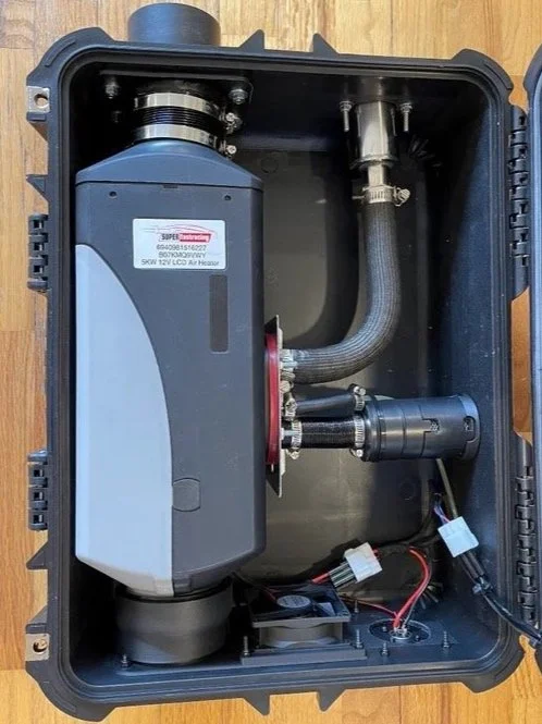
Diesel heaters work fairly simply. Let's look at the GIF to the right. The key to how a diesel heater works is the fact that the combustion intake and exhaust are SEPARATE from the air that is warmed and forced into the space. This is the key difference between a diesel heater and a simple propane heater you may have in your garage.
12V DC Power is applied to the ICU (Integrated Control Unit), turning on the heater’s control panel
The user then uses the control panel (not shown) to send a signal to the ICU, starting the startup procedure.
The ceramic glowplug is then heated rapidly, warming the combustion chamber.
This step takes the most amount of power by far. 12V, 40W is about 3.3 amps, meaning if the heater always drew this much power it would only run for about 7 hours and 15 minutes as I have 24ah of battery capacity onboard (24/3.3=7.27 hours).
Once the combustion chamber and glow plug have warmed, the fuel pump turns on, pumping small amounts of diesel fuel into the combustion chamber. At the same time, cold air is drawn through the combustion air inlet, mixed with the diesel fuel, and combustion occurs.
This then warms the heat exchanger (aluminum fin structure). The diesel exhaust is then exhausted through the exhaust outlet into the atmosphere, NOT the structure (tent).
Once the diesel heater has warmed the heat exchanger, the hot air fan turns on. This fan draws air from the atmosphere through the heater, over the heat exchanger, and out the hot air outlet. The hot air outlet is then plumbed into the structure, warming it.
What are some Issues that Could Arise?
There are two primary concerns, the first being fire/explosion. The reason for concern here is that the tank that holds the diesel fuel will be stored inside the case, next to the hot diesel heater core. The reason for this is because diesel fuel gels under 15°F and simply becomes unuseable. If the diesel fuel gels, the fuel pump will not be able to pump the fuel into the diesel heater core. Because I am going to be using this heater for ice fishing, I would estimate that over half the time where I would use this heater, it is going to be under 15°F. For this reason, the diesel fuel will be stored inside the container in hopes of keeping it at a more manageable temperature, however, I must be careful how hot the inside of the case becomes.
The second concern is carbon monoxide poisoning. Now I know the main point of using a diesel heater over a propane heater is to eliminate carbon monoxide poisoning, however, there is a chance that the exhaust fumes from the diesel heater will be sucked into the hot air inlet. These fumes would then be pushed into the tent. For this reason, I will also be using a carbon monoxide detector inside the tent and 3-D printing a 90° elbow for the intake to hopefully redirect where the air is pulled in from. I will also be routing the exhaust of the diesel heater to a different side of the case than the intake.
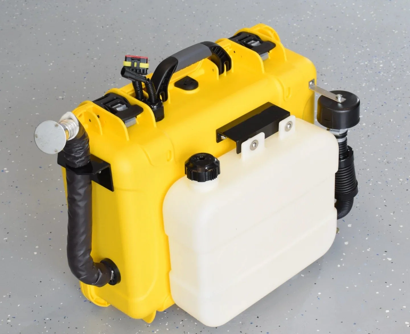
Shown to the right is an example of a diesel heater in a case without a diesel tank. In this situation, the tank is most likely mounted to the lid of the case.
Wiring
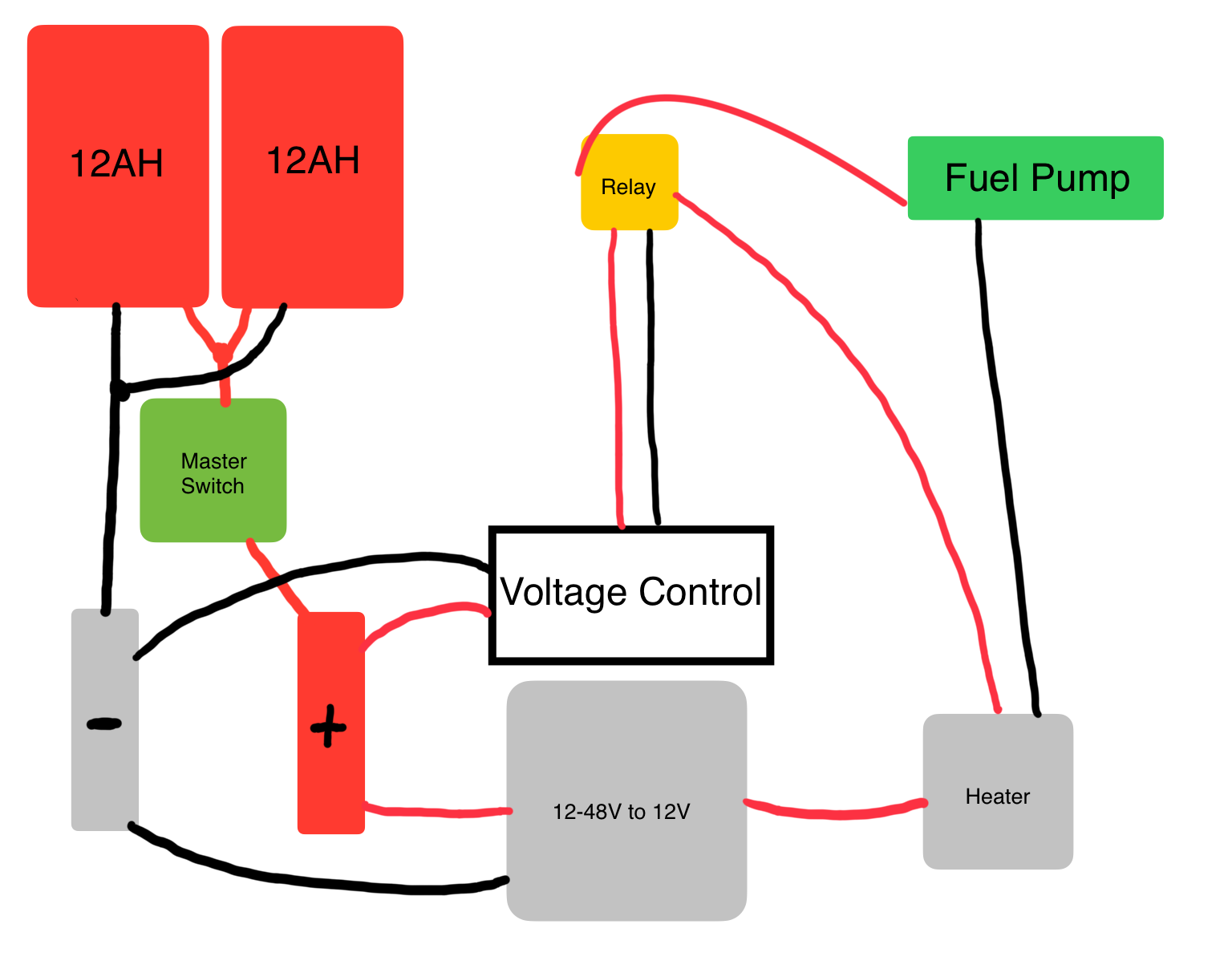
There are two different wiring segments to this diesel heater. The first is the diesel heaters internal wiring. This consists of the LCD panel, ICU and fuel pump. I am going to modify the connection to the fuel pump from the ICU with the second and more complicated segment of wiring. This is the wiring used to power the heater and the extra cooling fans as well as control wether or not the ICU can communicate with the fuel pump. This is more complicated because it is not prewired and the wiring is up to me. I have created a crude wiring diagram to try to explain my thinking.
On the left are my two Milwaukee 12ah battery packs wired in parallel. This is both for voltage control and for the ability to hot swap a battery. The total voltage coming out of the batteries will be around 20.60 volts, not 41.20 volts, however, the total amp hour capacity will be 24. The larger diameter wires (12G) will go to the diesel heater power in (glow plugs, lcd, hot air fan), however, secondary wires will go to a voltage control box that controls a relay. This relay, when closed, will allow power to flow to the fuel pump from the diesel heater ICU, enabling normal function. When open, no current will flow from the ICU to the fuel pump, cutting off the diesel supply to the heater core and glow plug. This will cause the ICU to fault and safely shutdown the heater before over draining the batteries. This is done through the voltage controller as when the batteries drain below 16.60 volts, it will open the relay. Once the batteries are recharged, the voltage control unit will close the relay again, allowing normal diesel heater operation.
This whole system is designed to keep the expensive lithium ion batteries safe and in their operational voltages (20.60 to 16.60 volts). Over charging or discharging lithium ion batteries will render them inoperable in the future, essentially killing the battery. The 20.60 volts is also stepped down to 12 volts to power the diesel heater, however, this does not effect the reading of the voltage controller, meaning that the voltage controller will be able to shut off the fuel pump (essentially the heater), when the voltage of the two batteries drops below 16.60 volts. This also allows me to pull a battery at any time and put in a freshly charged one without the heater shutting off, which is highly advantageous as the startup/down sequence is quite lengthy.
Two Options for Operation
Using Two Batteries Until Failure
Master Switch is turned on
Voltage control unit turns on
Voltage control unit turns on relay
Diesel Heater turns on
Voltage control unit reads 20.60 volts
Heater runs until battery(s) reach 16.60 volts
Voltage control unit turns off relay
Fuel pump turns off
ICU detects fault
ICU shuts down diesel heater
Master switch is turned off
User replaces batteries
Repeat
Replacing a Battery Before Shutdown
Master Switch is turned on
Voltage control unit turns on
Voltage control unit turns on relay
Diesel Heater turns on
Voltage control unit reads 20.60 volts
Heater runs until battery(s) reach 17 volts
Voltage control unit does not turn off relay
User takes out one battery
User puts in freshly charged battery
Voltage control unit reads about 19 volts
Repeat, replacing lower voltage battery